In The Circuit Diagram R1 In The Diagram R1 R2 R3
Solved for the circuit below, find the current through r1 Solved for the circuit shown, find the power across r1 R1 circuit shown value maximum absorb power will outline help
Answered: In the circuit shown, what value of R1… | bartleby
[solved]: from the circuit shown, calculate r1, explain in Q3. consider the following circuit diagram. if r1 −r2 =r1 =r1 −r3 =3ω, fi.. Solved problem 1 the diagram below shows a circuit where: r1
Solved complex circuit diagram r1 12 r4 6ω 10ω r2 15ω r5 3ω
Solved question 1:refer to diagram 1. -in the circuit: r1Solved 10. connect the circuit shown in figure 3. r1 1.00 r4 9. consider the circuit diagram as given below if r1 =r2 =r3 =r4 =r5 =3ω,..Consider the circuit in the diagram below in which r 10 ω.
Solved 1- in the circuit shown below, let r1 = 2 1, r2 = 3Solved the diagram below shows a circuit where; r1 = 5 ω, r2 Solved circuit r2 r1 shown let transcribed problem text been show hasSolved for the circuit shown, find the value of r1 that.

Solved consider the circuit shown. the components are r1
Solved transcribedSolved r1 r3 r2 r4 w the circuit in the diagram contains one Circuit diagram below resistors which r2 r1 given consider threeAnswered: in the circuit shown, what value of r1….
2009 r1 wiring diagram frontSolved for the circuit shown, determine r1 for the circuit 11. consider the circuit diagram as given below if r1 =r2 =r3 =r4 =r5 =3ω..Circuit complex diagram answer questions r1 r2 solved 6ω answers r5 r4 transcribed problem text been show has.

Solved calculate 𝑅1 in the below circuit.
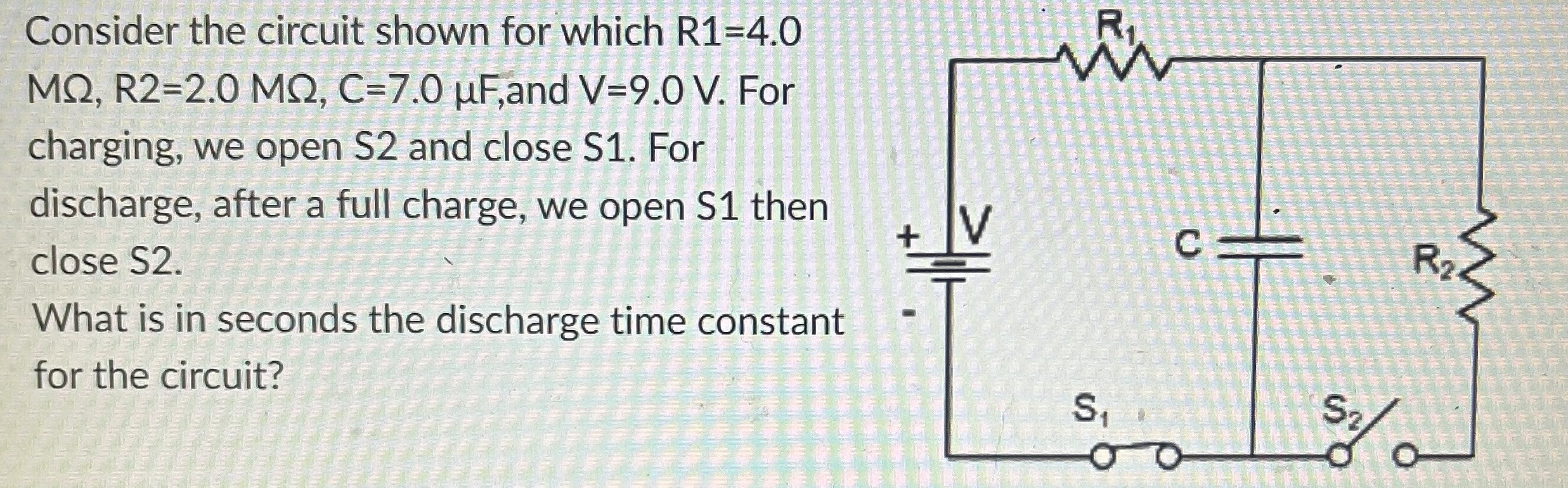
Solved the diagram below shows a circuit where; r_1 = 4.0Solved consider the circuit shown for which r1=4.0 mω, Solved refer to circuit diagram below. the r1=r2=r and both40 consider the circuit in the diagram below, in which r = 11 ω.
Ohm r1 circuit shown diagram solved complete please work showSolved for the circuit shown, the current through r1 would Solved consider the circuit shown in the diagram below, forSolved q1) in the circuit in the above figure r1 = 18 ω, r2.
Solved 3. a circuit diagram is shown below . r1 = 1.0 ohm ,
Solved for the circuit shown in the figure(figure 1), r1 40Solved required information consider the circuit in the Solved calculate from the circuit diagram: what value of r1Solved the diagram below shows a circuit where; r1 = 2.00 ω,.
Solved (25\%) problem 1: a circuit is constructed as shown[solved]: consider the circuit in the diagram. r1=8 r2=7, In the diagram r1 r2 r3.


![[Solved]: From the circuit shown, calculate R1, explain in](https://i2.wp.com/media.cheggcdn.com/media/ded/dedc1dc0-aa83-4674-b0c3-9e417037b03f/phpRq2PPv)


