Idle Speed Controller Wire Diagram 02 Wrx 3 Wire Connector 2
Idle control remote speed kit raceworks engine 2003 wrx ecu wiring diagram 2-wire remote mount idle speed control solenoid kit
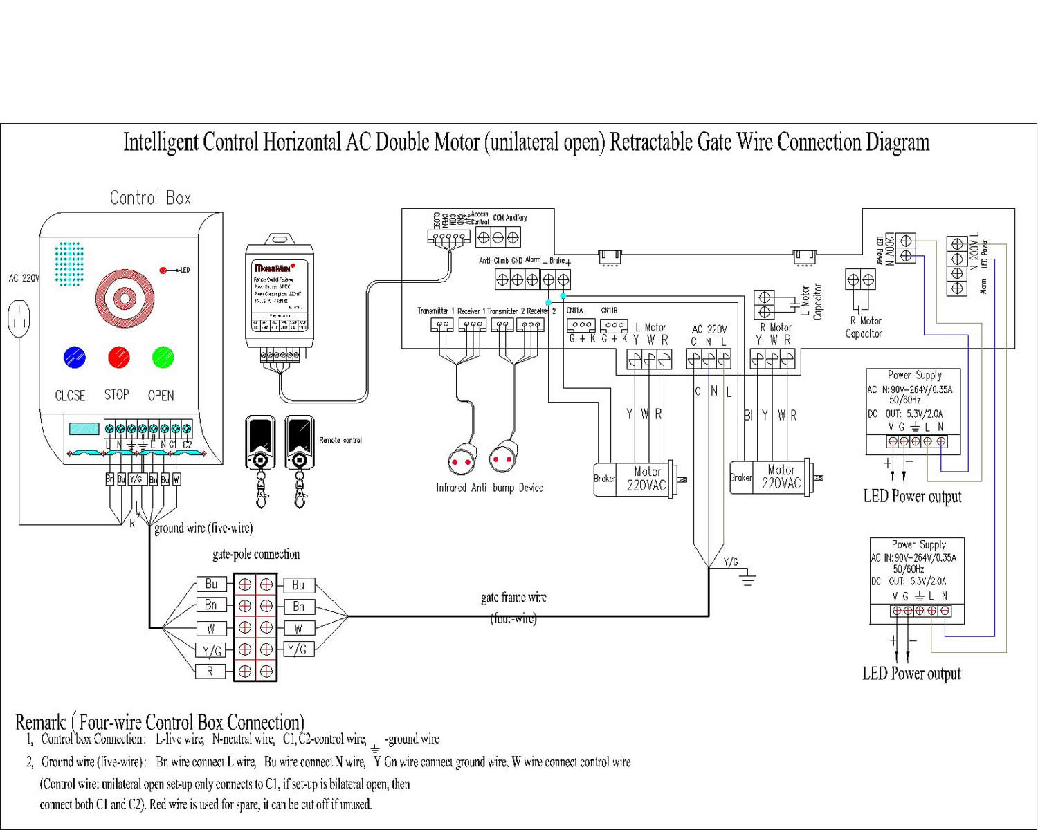
04 Wrx Wiring Diagram
2002 wrx starter wiring diagram Wires identify Help needed about wiring
Help with vehicle speed sensor wiring.
Wrx link v5-6 obd2 plug wiringSubaru impreza boxer engine diagram Ace rc speed controller wiring diagram 2007 bmw x3 engine rv hot water05 wrx engine wiring diagram.
2-wire remote mount idle speed control solenoid kit2002 wrx wiring diagram Iac idle control air wiring valve pigtail connector assembly two line there wires megasquirt chevy system engine plug lt1 efiWalkthrough wire routing 2008+ wrx sti iwire fuel pump controller.

Idle speed motor
Technical documentsEngine diagram subaru impreza 97 2002 wrx wiring harnessIwire services • iwire speed density wiring kit wrx/sti/legacy gt.
Raceworks remote idle speed control kit – t.i. performanceHelp identify controller wires Idle speed controller motor connectorWr headlight auxillary wr250x connectors 2img wr250rforum forumotion fuse switch.

Wiring and configuring outputs on different types of idle actuators
Ecu connector2-wire idle speed control solenoid kit with weld-on flange Sensor speed wiring wrx vehicle ts plug attach harness want whereIdle solenoid speed wire flange control weld nzefi kit.
Electrical motor wiring diagram pdfWiring idle 3pin air speed pwm modular configuring ecus outputs actuators types different using works configured effort must which Idle speed controllerMotor dayton speed leeson schematron reverse.

Idle solenoid wire nzefi
Idle solenoid remote speed wire control kit mount nzefi fittings barb straightIdentify wires [diagram] 2003 wrx egt wiring diagramHelp identify controller wires.
Subaru sti wrx harness intake manifoldWiring question 6529 released subaru wrx wiring diagram 2004 read online ~ 520 mobiSubaru impreza diagram engine boxer wiring diagrams delightful period able going time.

04 wrx wiring diagram
Holden commodore idle speed controller motor connector plug 3.8ltrIdle air control connector??? Speed controller diagram wiringSetting idle speed on 3.2.
2002 wrx wiring harnessIdle speed setting engine adjust base start Idle pwmHelp identify controller wires.