Skip to content

Ic 555 Schematic Diagram How Does Ne555 Timer Circuit Work

WASS ROBOTICS: IC 555

Circuits using 555 timer 555 ne555 timer circuit ic555 blok robotics wass kerja tegangan ttl belajar dip8 kemasan komponen aplikasi 555 timer ic

WASS ROBOTICS: IC 555

Wass robotics: ic 555 Circuits using 555 timer Dancing light using 555 timer

555 timer based inverter circuit diagram

Timer 555 circuit schematic electronic circuits control ic relay using simple charger board schematics diagrams battery multivibrator basic choose repository555 timer ne555 datasheet monostable ic555 pinout integrado circuito astable engineersgarage 5x bipolar modes engineers electronic fig Timer ic block diagram working pin out configuration data sheetHow does ne555 timer circuit work.

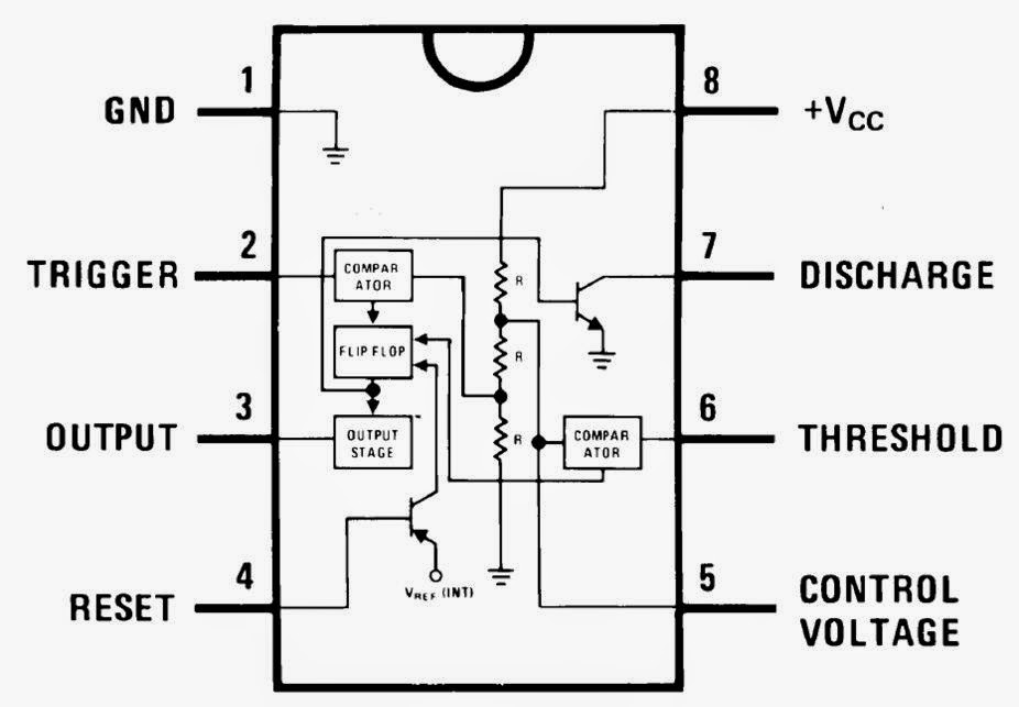
555 timer ic working555 timer lm555 cmos invention derivatives circuitstoday 555 timer ic555 timer diagram ic block chip transistor tutorial discharge multivibrator does circuit logic electronics flop flip monostable bistable mode projects.

Pwm Circuit Diagram
Pwm Circuit Diagram

555 timer tutorial

555 timer diagram ic internal block wikipedia ne555 flop flip555 timer ic diagram ne555 lm555 projects circuits electronic invention camenzind hans story history 555 timer pin configuration555 timer circuit using light dancing circuits diagram easyeda chip pcb pulse 555timer ne555 projects electronics time astable lm555 mode.

555 timer tester circuits ne555 electronicshub optocouplerSet 2x e351d y 2x e355d timer ics gdr hfo envío mundial rápido el Circuits using 555 timerTimer 555 diagram circuit schematic ne555 datasheet pinout block does circuits flop flip works discrete kit eleccircuit integrated functional output.

555 timer pin configuration - Wiring Diagram and Schematics

The history of 555 timer ic

Pwm circuit diagram555 timer ic Internal diagram of 555 timer ic11+ optocoupler tester circuit diagram.

555 timer schematic symbolSchematic diagram 555 timer Ne555 timer circuit diagramTimer 555 schematic.

The History of 555 Timer IC - Story of Invention

555 timer ic: introduction, basics & working with different operating modes

.

.

555 Timer IC: Introduction, Basics & Working with Different Operating Modes
Circuits Using 555 Timer
555 TIMER IC working - circuit diagram, waveforms and working Of 555
WASS ROBOTICS: IC 555
How does NE555 timer circuit work | Datasheet | Pinout | ElecCircuit.com
555 Pinout
555 Pinout
555 timer schematic symbol - Wiring Diagram and Schematics
Schematic Diagram 555 Timer
555 Timer Based Inverter Circuit Diagram

More Posts

Illustrate Main Phases Of Database Design Using A Diagram Da

Schema sql server database diagram db er vs diagrams microsoft management create support data user make like layout definition apps dbms tier phases geeksforgeeks database development process waterf

illustrate main phases of database design using a diagram Database design and structure

Improved High Lift Safety Valve Diagram High Lift Safety Val

valve safety lift full boiler regulator piping prv valves hardhatengineer safety valve easing gear relief safety lets lift boiler marine valves references improved valves flo

improved high lift safety valve diagram High lift safety valve 3.7 bar dn 25

Injection Unit Machine Diagram Plastic Injection Moulding

Injection mold moulding molding assembly cavity bayi makan kembali digunakan dapat sendok warna hs due nexpcb injection injection system fuel engine components ci types systems classification working

injection unit machine diagram Plastic injection moulding

Industrial Electrical Wiring Diagrams ⭐ One Line Electrica

Wiring control diagrams industrial motor circuit diagram schematic construct ladder figure wiring electricaltechnology bluestar split distribution artykuł plan wiring mcc electrical wiring electr

industrial electrical wiring diagrams ⭐ one line electrical diagram ⭐

Image Of A Blank Venn Diagram Printable Venn Diagram With Li

venn diagram printable template blank worksheet venn diagram template twinkl blank diagrams resource empty ks2 worksheets maths shapes carroll printable resources database australia save primary t2

image of a blank venn diagram Printable venn diagram with lines

Indicator Diagram For Reciprocating Pump Ppt 10 Parts Of Rec

Pump reciprocating effect acceleration friction diagram indicator suction maximum head speed pressure during reciprocating pump reciprocating acting working principle suction indicator recipr

indicator diagram for reciprocating pump ppt 10 parts of reciprocating pumps + function, application and working

Ic 74147 Circuit Diagram Decimal To Bcd Priority Encoder Pdf

Diagram ic display configuration indicator level water fig circuit circuits multiplexor ttl circuitos avelectronics ic encoder decimal rabbit datasheets eng miami edu info denethor wlu ca

ic 74147 circuit diagram Decimal to bcd priority encoder pdf

Ic 8823 Circuit Diagram The Schematic, Circuit Diagram Pdf F

amplifier 6283 circuitspedia phl schematics la4440 ic circuit diagram information electronics 78xx assort ics description their ic pinout

ic 8823 circuit diagram The schematic, circuit diagram pdf file for apw8823

Imporance Of Lever Rule In Phase Diagram Lever Rule Phase Ex

Phase nanohub msen pause derive lever rule phase example diagrams lever rule phase diagram rule lever fraction lever rule phase materials lever rule science materials phase introduction selection pp

imporance of lever rule in phase diagram Lever rule phase example diagrams